Europa Challenge 2016 - Extrusion vector data and EPSG support
Improving the integration of NWW in gvSIG Desktop: Extrusion, vector data and EPSG support
We have continued improving the integration of NWW and gvSIG Desktop to have a more powerful open source 3D GIS. We have developed the support of all coordinate reference systems 2D Views in 3D Views (now gvSIG can reproject any 2D View to 3D View), the support of vector data and the integration of LiDAR Data in gvSIG, animations, anaglyph mode and tools to made the extrusion in gvSIG.
At the current time there are 3 different loading modes for vector layers: 1) Rasterized vector . 2) Vector: the features from the gvSIG vector layer will be transformed into 3d vectors. 3)Extruded Vector (to obtain an effect of volume).
Demos
Extrusion in gvSIG: https://youtu.be/gBVRxBF9PJQ
EPSG Support: https://youtu.be/6W4rur_9l8o
LIDAR data in gvSIG 3D plugin: https://youtu.be/-do5RfpJRCY
Animation: https://youtu.be/aFxKpNevrlM
3D View: Anaglyph mode: https://youtu.be/tiYFnuNa7N8
Teide vulcano in Canary Islands demonstrated on gvSIG 3D plugin: https://youtu.be/RNATZrjUV2I
gvSIG Desktop
gvSIG Desktop is a a powerful, user-friendly, interoperable GIS used by thousands of users worldwide. It is easy to work in a variety of formats with gvSIG Desktop, vector and raster files, databases and remote services. There are always available all kinds of tools to analyze and manage your geographic information.
gvSIG Desktop is designed to be an easily extensible solution, allowing thus continually improving the software application and developing tailor made solutions.
gvSIG Desktop is open source software, GNU / GPL license, this makes its free use, distribution, study and improvement.
The gvSIG firts version was born in 2004 within a project that consisted in a full migration of the information technology systems of the Generalitat Valenciana in Spain (Valencian Regional Government). Since 2010, the project is managed by gvSIG Association.
New 3D View Plugin features
3D View is a plugin for gvSIG Desktop based on NASA WorldWind SDK that allows users to create 3D views from gvSIG 2D views.
From the version 2.3 of gvSIG on, a 3d is available which allows the user to visualize layers in a Nasa World Wind 3d view. The user can select several loading modes for the layers.
Vector layers in the 3d view.
The 3d properties of a vector layer can be accessed by right clicking on the layer and accessing the Properties entry in the context menu. By default the 3D tab will show up like this:
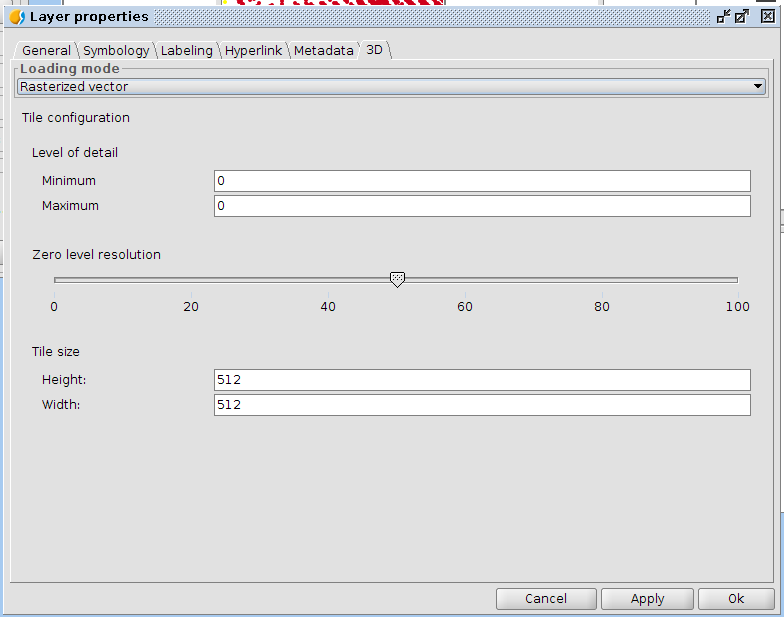
At the current time there are 3 different loading modes for vector layers:
- Rasterized vector: the gvSIG vector layer will be rasterized as an image over the 3d view
- Vector: the features from the gvSIG vector layer will be transformed into 3d vectors and loaded in the 3d view
- Extruded Vector: the features from the gvSIG vector layer will be transformed into 3d vectors and loaded in the 3d view, with an applied extrusion, in order to obtain an effect of volume.
The following sections explain the different loading modes.
Rasterized vector
It’s not a new feature (see gvSIG Desktop 2.2 manual)
Vector
The Vector loading mode presents the following user interface:
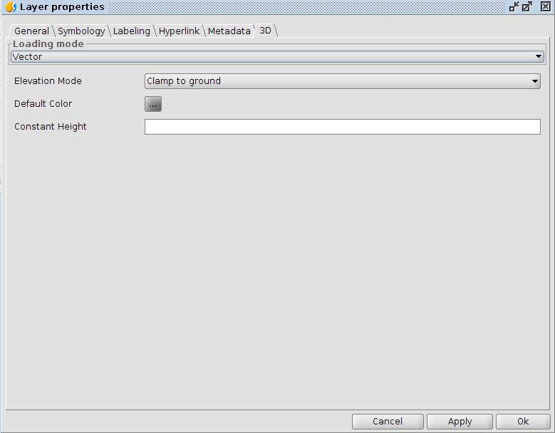
The altitude of the features can be defined by two factors (and also be the sum of both):
- the 3rd dimension of the geometry, if available (3d shapefiles for example)
- the Constant Height parameter
There are 3 available elevation modes, which will consider the altitude differently:
- clamp to ground: in this case the features are clamped to the elevation model currently used in the 3d view. In this case the altitude definition will not be considered.
- absolute: in this case the elevation of the vector is given by the altitude, defined as absolute elevation over the sea level.
- relative to ground: in this case the elevation of the vector is given by the altitude, defined as relative elevation over the terrain.
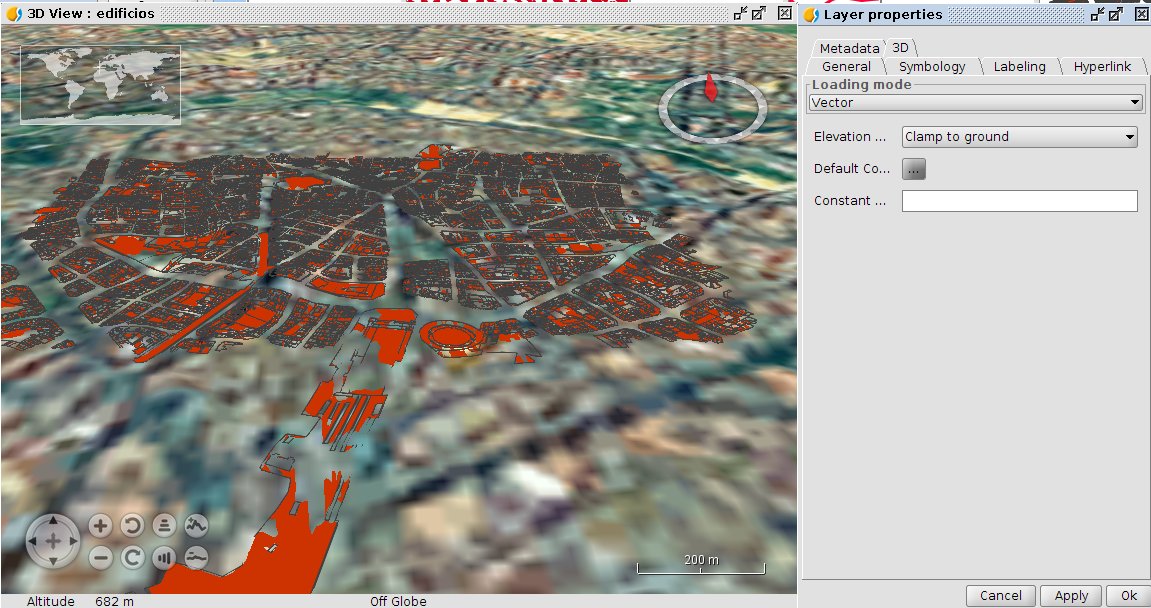
For example this is how the clamp to ground option would look like:
We can see that the very coarse default terrain model in many parts covers the vectors. In this case it is possible to set the mode to relative to ground and apply a constant height to solve it:
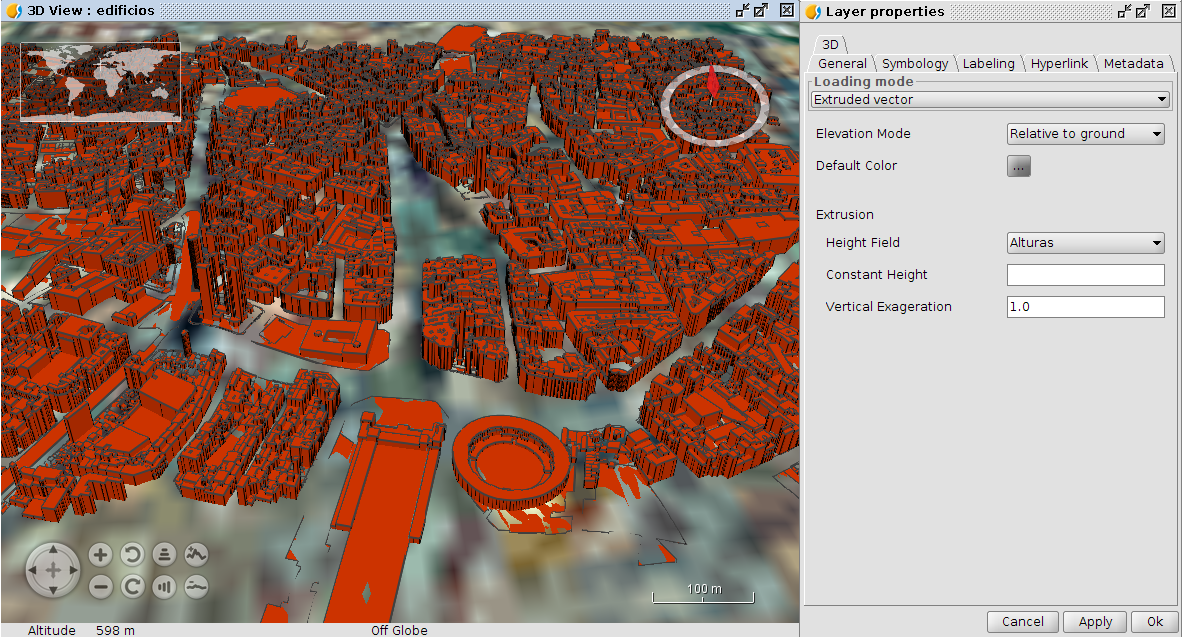
Extruded vector
The extruded vector loading mode adds a couple of parameters to the user interface:

In this caes thee altitude of the features can be defined by four factors:
- the 3rd dimension of the geometry, if available (3d shapefiles for example)
- a Height Field from the attributes table
- the Constant Height parameter
- the Vertical Exageration, which is a multiplication factor applied to the height
There are 2 available elevation modes, which will consider the altitude differently:
- absolute: in this case the elevation of the vector is given by the altitude, defined as absolute elevation over the sea level.
- relative to ground: in this case the elevation of the vector is given by the altitude, defined as relative elevation over the terrain.
For example, if we select the relative to ground option and apply an height field that contains the building heights, this will look like:
Again we can apply a constant height to elevate the features over the terrain. Let's also try to use the number of the floors of the buildings instead of the altitude. In this cas we can apply a vertical exaggeration of 3 meters to simulate the correct building altitude:
Other examples
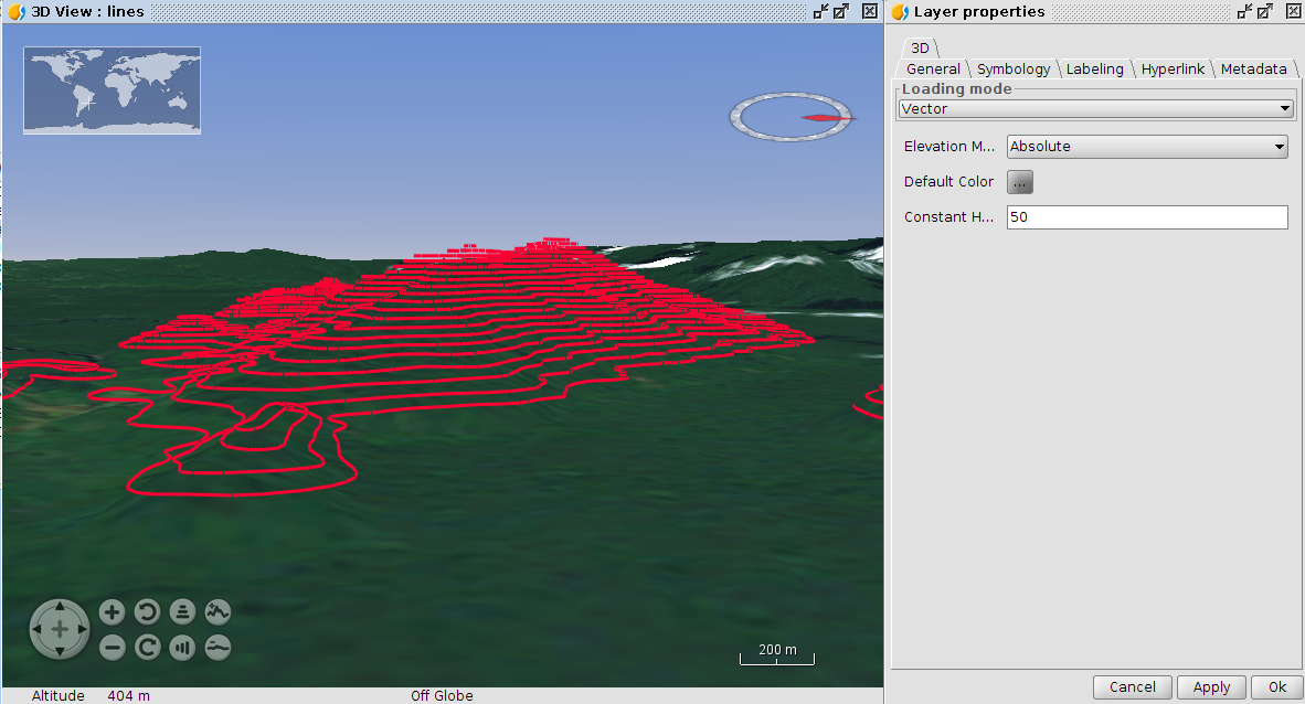
Example of a lines layer of isolines that have 3d coordinates. Here the extruded mode was selected and the absolute elevation mode was picked adding also a constant height of 50 additional meters:
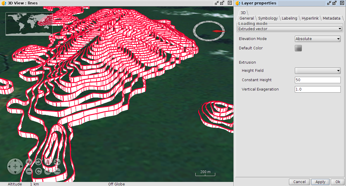
The same layer and parameters, but without extrusion:
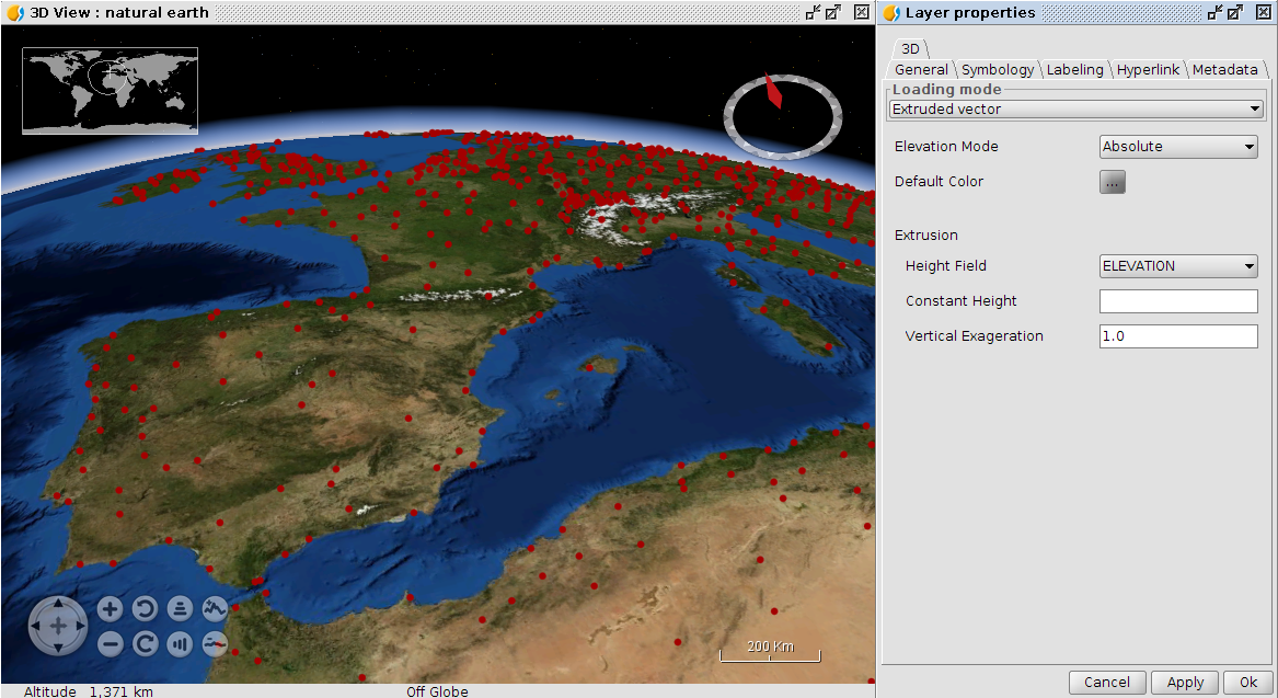
An example of points layer that do not have 3rd coordinates, but an absolute elevation in the attributes table. In this case the extrusion was picked and the absolute height taken from the elevation field in the attributes table:

Since the elevation is the one of the terrain, it is not possible to appreciate the extrusion effect. By adding a constant height to add as an offset, this is solved:
Other new features
- Complete support of the projections database in 3D Views (in gvSIG 2.2 only supports EPSG:4326), so raster reprojection from 2D to 3D.
- LiDAR data access and management (in 2D Views as well as in 3D ones). More info: https://blog.gvsig.org/2016/06/20/towards-gvsig-2-3-lidar-data/
- Animations manager. To create, edit, delete and playback animations on 3D views.
- Anaglyph 3D. Enable or disable the anaglyph mode in 3D views.
gvSIG Desktop and urban management solutions
Smart City, the intelligent city, has been one of the most fashion concepts in recent years dealing mainly with the use of ICT, information and communication technology, to improve citizens living standards.
What is the role of geomatics technologies for Smart City land management? They are the cornerstone; more than 80% of the information handled by a municipality are geographically located: infrastructures, artistic heritage, parks and gardens, socio-economic components, investment … everything is or can be spatially represented.
gvSIG Desktop is used in a big number of local governments, around the world. We think that 3D tools will be essential (and amazing!) tools to manage the cities.
Binaries and portable versions
http://www.gvsig.com/en/products/gvsig-desktop/development-versions-downloads
Sources
gvSIG Desktop: https://redmine.gvsig.net/redmine/projects/gvsig-desktop/repository
3D View: https://redmine.gvsig.net/redmine/projects/gvsig-3d/repository/show/2.1/branches/org.gvsig.view3d_vector_and_extrusion_2.3/org.gvsig.view3d